Raspberry Pi Lane Tracking Robot Car
The Idea
The goal was to create a simple and affordable robotics platform. The Raspberry Pi was the perfect brain for the project. It's powerful enough for real-time image processing with OpenCV and accessible for hobbyists. The concept was to use a webcam to see the road, process the image to find the lane and steer the motors to follow the desired path.
Hardware & Software
Hardware
- › Raspberry Pi 3 Model B+: the compute brain running the CV pipeline and motor logic
- › L298N Motor Driver: dual H-bridge IC controlling speed and direction of all four DC motors via PWM signals from the Pi
- › 4× 6V DC motors + wheels, two on each side for differential steering
- › USB webcam: the car's only sensor, mounted on the upper deck
- › 9–10V battery pack: powers the motors independently from the Pi's supply
- › Custom 3D-printed chassis: designed and printed to precise specifications
Software
- › Python 3.10+: all control and CV logic
- › Raspberry Pi OS Lite 64-bit: headless OS to minimize overhead and maximize performance
- › OpenCV: camera capture, color-space conversion, masking, contour detection, and centroid calculation
- › uv: fast, reproducible dependency management via
pyproject.toml
Chassis Layout
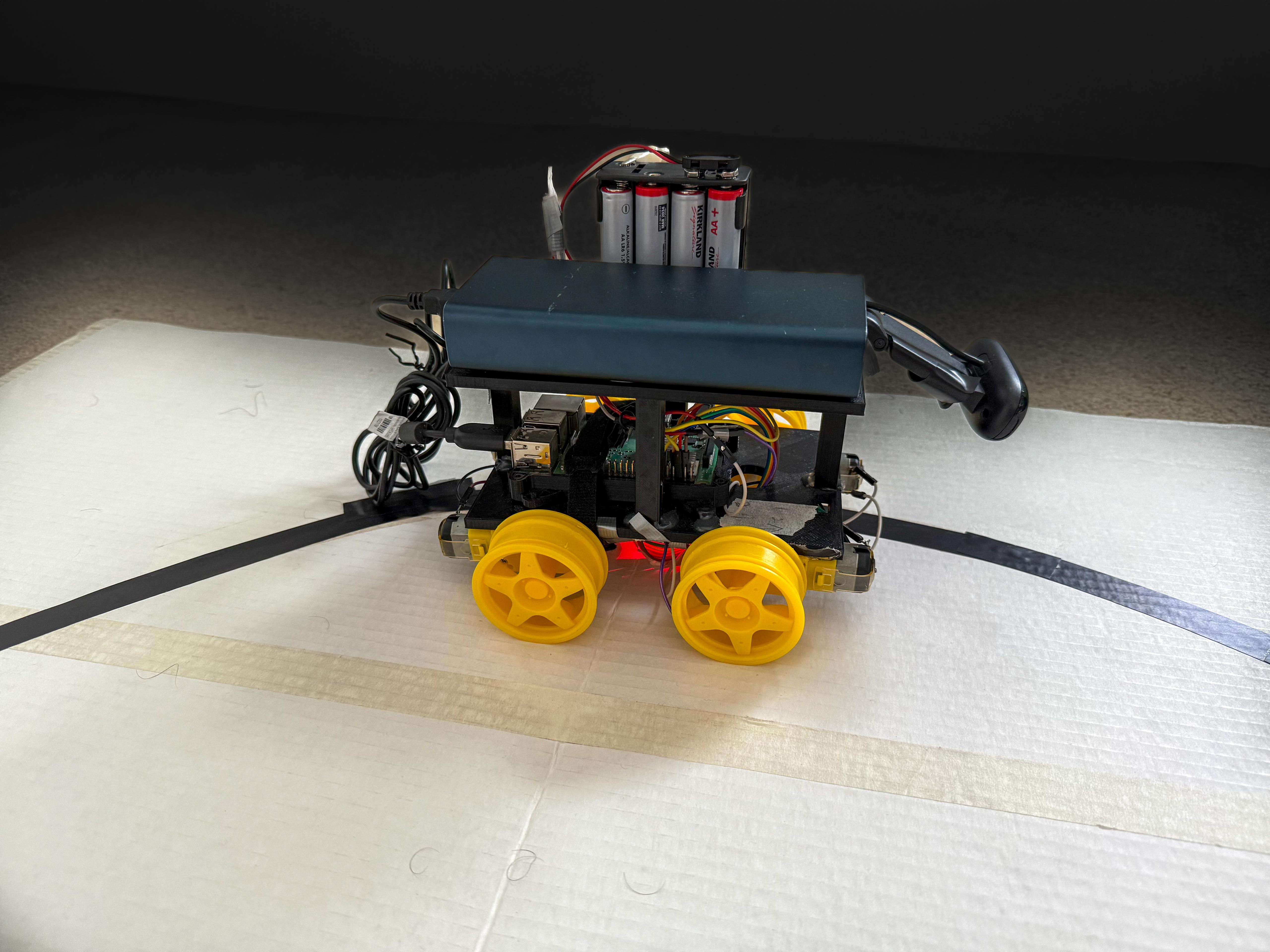
The chassis was custom-designed in CAD and 3D-printed to precise tolerances, organized into three distinct tiers to cleanly separate concerns.
Bottom Level: Drivetrain
Houses the four DC motors and the L298N H-bridge controller. This is the mechanical and electrical foundation; all motor wiring terminates here before signals are routed up to the Pi.
Middle Level: Compute
The Raspberry Pi sits here, connected to the motor driver below via GPIO pins. Extra space was deliberately left for future sensor modules (IMU, ultrasonic, or LiDAR) without requiring a chassis redesign.
Upper Level: Power & Sensing
The battery pack and USB webcam live on the top deck. Mounting the camera high and forward gives a clean, unobstructed view of the track ahead.


Frame Threshold
The first working version is built on a simple and intuitive principle: frame-threshold logic. The camera captures the view ahead, and the software divides the frame into left and right sections. If more lane pixels are detected on the left, the car interprets that as drifting right and steers left, and vice versa.
There's no measurement of how far off-center the car is, only which side has more lane. The steering command is essentially binary: go left, go right, or go straight.
How It Works
- Capture a frame from the webcam
- Convert to Grayscale color space and apply a color mask to isolate lane markings
- Count the lane pixels in the left half vs. the right half of the frame
- If left > right → steer left; if right > left → steer right; otherwise → go straight
- Send the corresponding PWM signal to the L298N motor driver
The result: the car made it through the track, but barely. Movement was choppy and inefficient, with the robot constantly overcorrecting and zigzagging from side to side. It proved the concept works, but exposed the fundamental limitation of a purely reactive, stateless control system: it has no sense of magnitude.
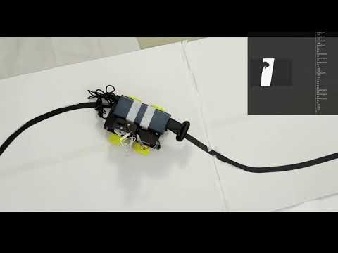
v5 Demo: Frame Threshold
Reactive, binary steering. The zigzagging highlights exactly why threshold logic isn't enough.
PID Control
Version 6 rethinks the control strategy from the ground up by introducing a Proportional-Integral-Derivative (PID) controller.
Instead of asking "which side has more lane?", the algorithm now asks "where exactly is the center of the lane?" Using OpenCV's contour detection, the software finds the largest lane contour in the frame and computes its centroid (the precise geometric center of the detected lane region). The horizontal distance between this centroid and the center of the frame becomes the error signal.
This error is fed into the PID controller on every frame, which computes a steering correction that is proportional, cumulative, and predictive, rather than just reactive.
Proportional (P)
Scales the steering correction directly to the current error. A larger offset from center produces a larger correction. This is the main driving term.
Integral (I)
Accumulates past errors over time. If the car consistently drifts slightly in one direction (perhaps due to motor asymmetry), the integral term builds up and corrects for it.
Derivative (D)
Measures the rate of change of the error. If the error is shrinking quickly, the derivative term reduces the correction to prevent overshoot. This is what eliminates the zigzag.
Control Loop (per frame)
- Capture frame → convert to Grayscale → apply lane color mask
- Find contours → select the largest → compute centroid via image moments
- Calculate error = centroid_x − frame_center_x
- PID output = Kp × error + Ki × ∫error dt + Kd × (Δerror / Δt)
- Map PID output to differential motor speeds and write PWM to L298N
The result: the PID controller allows the car to make gradual, proportionate adjustments rather than snapping between extremes. The car glides through the track smoothly, continuously correcting small deviations before they become large ones. The improvement over v5 is immediately visible.
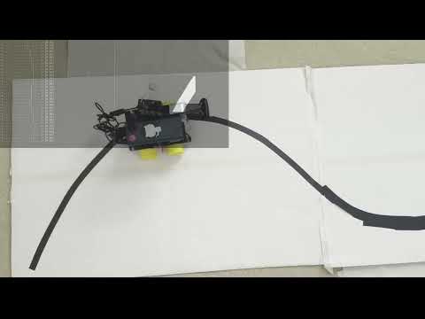
v6 Demo: PID Controller
Smooth, precise lane following with continuous error correction.