Autonomous F1Tenth Racer
A reactive, LiDAR-only racing controller for unknown tracks.
TL;DR
A 1/10th-scale autonomous race car that drives an unknown track using live LiDAR scans. The controller picks its speed and steering from what it sees in front of it and on its sides. Final run: 3 laps, 51 seconds, zero collisions.
Full project writeup is also hosted at the ECE 484 project site.
The Run
Three laps, no collisions, no map. Annotations as it goes:
- ›0:03. Long straight, car at max speed.
- ›0:07. Approaches a turn; front-cone distance shrinks, speed drops.
- ›0:11. Hairpin; both the front distance and the track width close in, so the car slows further.
The Car (Hardware)
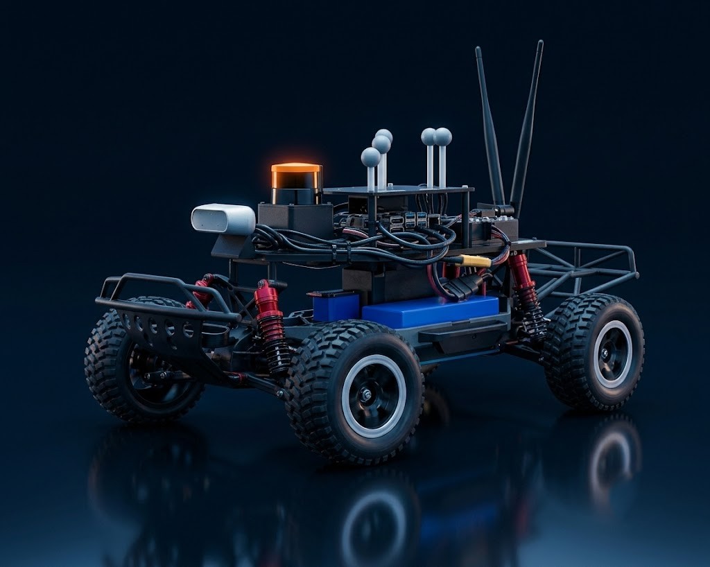
This is a standard F1Tenth car, the reference 1/10th-scale autonomy research platform out of Penn. Full hardware stack:
- ›LiDAR. Hokuyo UST-10LX, 2D planar laser scanner mounted on top of the deck. This is the only sensor we used at race time.
- ›Compute. NVIDIA Jetson Orin Nano running ROS.
- ›Motor controller. VESC 6 (electronic speed controller for the brushless drivetrain).
- ›Power. LiPo battery feeding both drivetrain and compute through a power distribution board.
- ›Chassis. 1:10 Traxxas with metal shock absorbers.
- ›Connectivity. Onboard WiFi antennas for remote ROS bag streaming and debugging.
- ›Tracking. Vicon markers on top of the car (used by the lab's motion-capture setup, not by our race code).
- ›Input. Remote controller for the dead-man switch and manual override.
System Architecture
Three nodes run in parallel at race time:
- Teleop. Handles joystick input and gates the motor enable.
- LiDAR driver. Publishes
/scanat the sensor's native rate. - Race controller. Subscribes to
/scan, computes steering and speed, publishes anAckermannDriveStampedcommand.
The loop, per scan:
Inputs
LiDAR scan + joystick enable
Feature
Front-cone distance
Feature
Track-width estimate
Feature
Left/right wall distance
Controller
Speed
Controller
Steering PID
Output Topic
AckermannDriveStamped
Car motion
The whole loop closes on every LiDAR frame. No memory of past laps, no global state.
Approach
We started the semester planning to do this with SLAM: map the track on a formation lap, localize against the map on race laps, and run a fast trajectory. We got it working in simulation, but it didn't survive the jump to the physical car (more on that in Challenges). Once SLAM was off the table for race day, we pivoted to iterating on the staff-provided EOH wall-follower script and pushing it as far as it would go.
Speed Controller
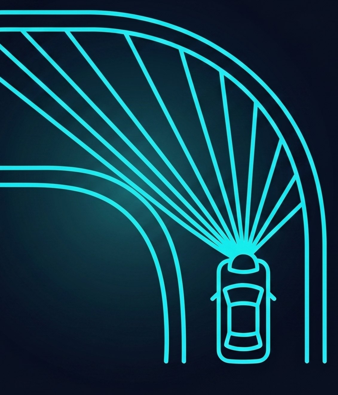
The default EOH controller scales speed linearly with the minimum distance inside a ±10° cone in front of the car. Reasonable baseline, but that cone is wide enough that the LiDAR starts catching the sides of the track when you approach a turn, so the car thinks there's an obstacle before there actually is one in its driving line.
We narrowed the front cone to ±5°. That alone made the car much more willing to commit to corners.
The bigger change: we added a second input to the speed law, track width. The intuition is that front distance tells you how far ahead is clear, but track width tells you how forgiving the geometry around you is. A narrow chute deserves a slower speed even if nothing is directly ahead.
To estimate width: the LiDAR returns a sorted array indexed by angle. We find the index that separates "wall on my left" from "wall on my right" (effectively the front of the scan), then take the minimum range on each side. The sum of those two is our track-width estimate.
Speed then becomes a linear function of both the narrowed front distance and that left+right wall sum, with tuning constants we found empirically.
Special Cases
A few corner cases we handled outside the main speed law:
- ›Minimum speed floor of 1.5 m/s. Below this the motor stutters
- ›Startup boost. For the first 0.33 seconds after enable, force speed to 5 m/s to punch past the stutter band.
- ›No-wall fallback. If the front cone returns no valid range, default to a conservative low speed instead of trusting garbage.
- ›Long-straight max. If the front wall is more than 13 m out, just commit to max speed. The geometry won't sneak up on us at that range.
Steering Controller
We kept the Base PID structure for steering and just retuned the gains. Process was the usual:
- Crank up P until the car can complete the tightest turn on the track.
- Increase D until straight-line oscillation is acceptable.
- I was minimal. Didn't need it
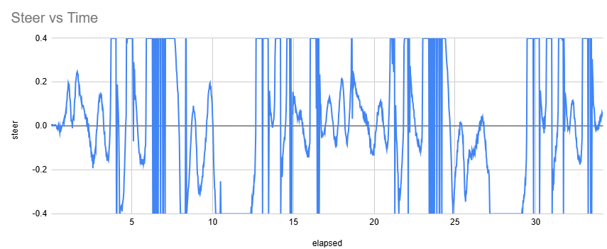
We also clipped the final steering angle to [-0.4, 0.4] rad, which protects against weird scan returns commanding a hard-lock turn.
Evaluation
Without localization there's no ground-truth pose to evaluate against, so we instrumented the controller itself instead and looked at three things: how it reacts to the scan, how cleanly it tracks its own speed targets, and how much safety margin it actually maintains.
Sensor Responsiveness
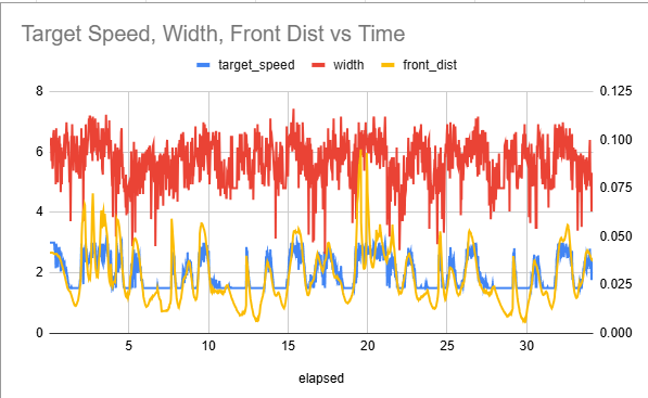
Plotting target speed vs. front distance and track width over time shows the controller doing what it's supposed to: open up the track and the target climbs, tighten it down and the target drops. Transitions are sharp and they line up with where the corners actually are on the track.
Speed Tracking and Ramping
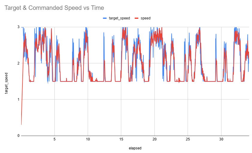
Target speed and commanded speed don't match exactly, and that's on purpose. We added accel/decel ramping so the car doesn't slam between speeds. Small jumps would otherwise translate into traction loss on the rear wheels.
Safety
Two main safety knobs:
- ›Steering clipped to ±0.4 rad no matter what the PID asks for.
- ›Minimum clearance of 0.3 m. We tuned the speed constants so that under normal track geometry the car never closes inside 0.3 m of the front wall.
Results
3 laps in 51 seconds
no collisions
Speed and steering both adapt to what the LiDAR sees. Open tracks get fast laps, tight sections get cautious approaches, all without any reliance on a map or a localization pipeline. For a controller this simple, that's a result we're happy with.
In Simulation
- ›Built a SLAM map of the track.
- ›Localized the simulated car against the generated map.
On the Physical Car
- ›Got scan-matching SLAM running on small tracks.
- ›Tuned the reactive controller to drive the full track reliably.
What We Tried First: SLAM
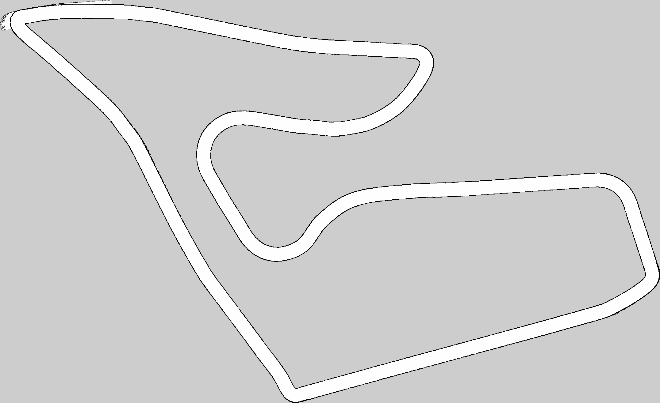
Before we landed on the LiDAR-only controller, the plan was a formation-lap-then-race strategy. Map the track once with SLAM, localize against that map on every subsequent lap, run a faster, map-aware policy.
In simulation this worked.
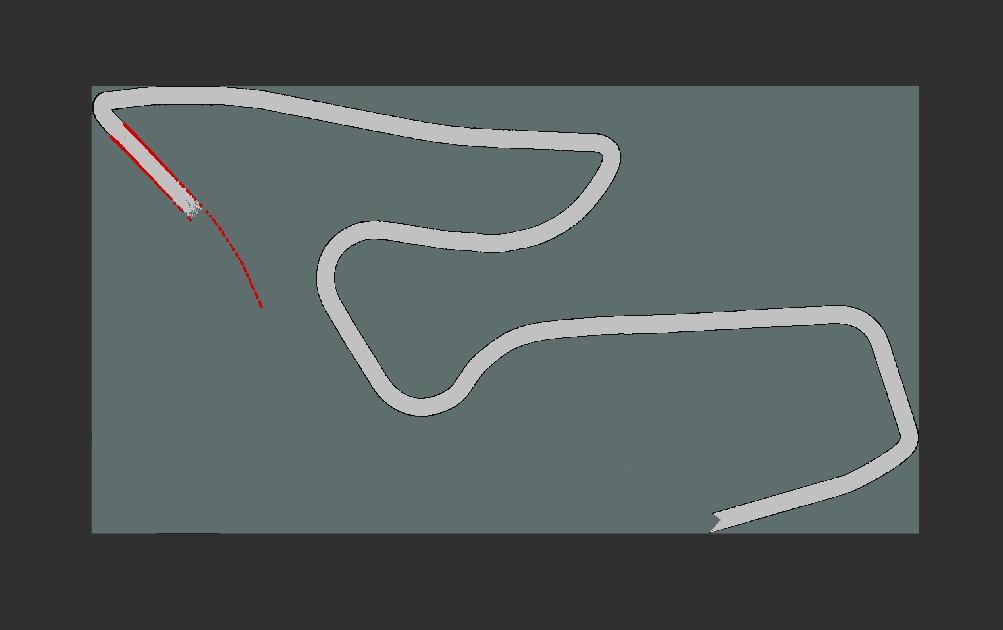
We also got AMCL localization working in the sim. The green dot is the simulator's ground-truth pose, the red dot is what AMCL was predicting from LiDAR alone:
It just didn't survive the move to the real car. Details below.
Challenges
1. Motor / Starting Torque
Early on, the car we were assigned (Car 1) had inconsistent starting torque. From a standstill it would either lurch or hesitate, which made tuning anything off a stopped start basically impossible. Every run started from a different initial condition.
Fix for race day. Motor calibration plus the startup-boost trick described above (force 5 m/s for 0.33 s) to power through the stutter band before settling into the real speed law.
2. SLAM Sim-to-Real Gap
Our simulated SLAM and AMCL stack was working cleanly. On the physical car it wasn't. The sim doesn't capture the actual noise characteristics of the Hokuyo, the actual vibration of the chassis, or the actual latency between scan timestamp and the control loop. Once any of those drift, AMCL's confidence estimate drifts with them. We could not get localization accurate enough to trust on race day.
3. Scan Matching Without Odometry
With full SLAM not working, we fell back to scan-matching-only approaches (Cartographer, SLAM Toolbox). These worked on small tracks where the loop closes quickly, like the CSL studio room:
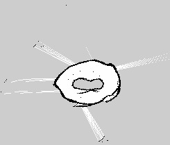
But on the larger competition track, with longer loops, the map drifted before it could close. That left us with artifacts and a localization estimate that wasn't usable:
This is the point at which we cut our losses and committed to the reactive controller.
Future Work
A few directions where this project could keep going:
- ›Visual odometry. A camera-based odometry source would give SLAM enough of a motion prior to actually close loops on bigger tracks. The D435i is already on the car, it's just unused right now.
- ›Wheel encoders. A real velocity signal from the wheels would close one of the biggest sim-to-real gaps in the stack. The VESC reports something, but it's not clean enough to trust for SLAM.
- ›Map-aware overlay. Once localization is reliable, the reactive controller could be augmented (not replaced) by a global racing line. Reactive for safety, planned for speed.
Contributors
Built with Siddarth Pattisapu and Soumil Kushwaha for ECE 484: Principles of Safe Autonomy, University of Illinois Urbana-Champaign, Spring 2026.