STM32 Security Sentry
Overview
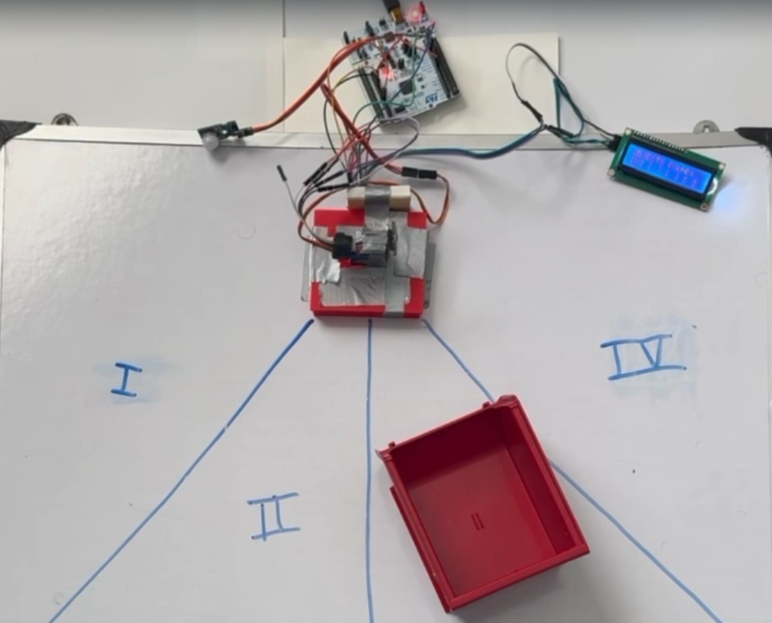
This project is a stationary sentry system built on the STM32F401RE NUCLEO platform to monitor and protect four physical sectors. The system integrates PIR motion detection, Time-of-Flight (ToF) LiDAR ranging, and mechanical actuation within a clean Finite State Machine (FSM). Unlike simple looping Arduino-style designs, it uses a bare-metal HAL-based approach without an RTOS, relying on hardware interrupts (EXTI) for event-driven responsiveness and non-blocking timers for real-time scanning, control, and state transitions.
The system mimics a radar station:
- Sleeps until motion is detected (PIR).
- Wakes and performs a mechanical sweep of the area (Servo + LiDAR).
- Maps intrusions into specific sectors.
- Notifies the user and enters a "Protect Mode" loop with active scanning if the threat persists.
System Demo
Watch full demo video here: https://youtu.be/kZfAan9jCs8
Hardware Architecture
| Component | Role | Interface | Protocol |
|---|---|---|---|
| STM32F401RE NUCLEO | Primary Controller | - | - |
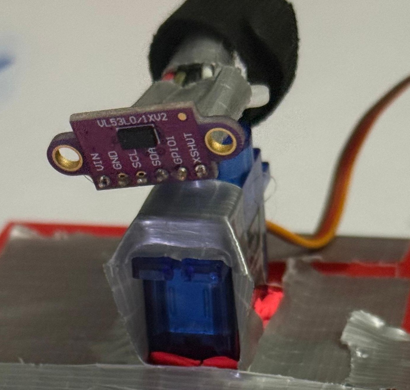
| VL53L0X LiDAR | Precision Ranging | I2C1 | I2C |
| HC-SR501 PIR | Motion Trigger | PA9 | EXTI (Interrupt) |
| SG90 Servo | Pan Mechanism | TIM2 CH1 | PWM |
| 16x2 LCD | User Interface | I2C1 | I2C |
Hardware Setup
Software Architecture: Finite State Machine
The core logic replaces standard blocking delays with a 3-Stage Finite State Machine. This allows the CPU to process sensor data and update the display simultaneously while managing mechanical movement physics.
1. IDLE (Low Power / Monitor)
- ›Behavior: The system is static. The servo is parked at 0°. The CPU waits for an external interrupt from the PIR sensor.
- ›Logic:
motionDetectedflag is set viaHAL_GPIO_EXTI_Callback. - ›Transition: Motion → SCAN.
2. SCAN (Active Mapping)
- ›Behavior: The servo sweeps 0° to 180° in 10° increments.
- ›Physics Handling: The system reads the LiDAR data from the stable current position before moving the servo to the next angle, preventing "blurry" sensor data caused by motor vibration.
- ›Data Processing: Distance data (< 500mm) is mapped into one of 4 angular sectors (45° slices).
- ›Transition: Sweep Complete (180°) → NOTIFY.
3. NOTIFY (Decision & Feedback)
- ›Behavior: The system analyzes the sector map.
Intruder Logic:
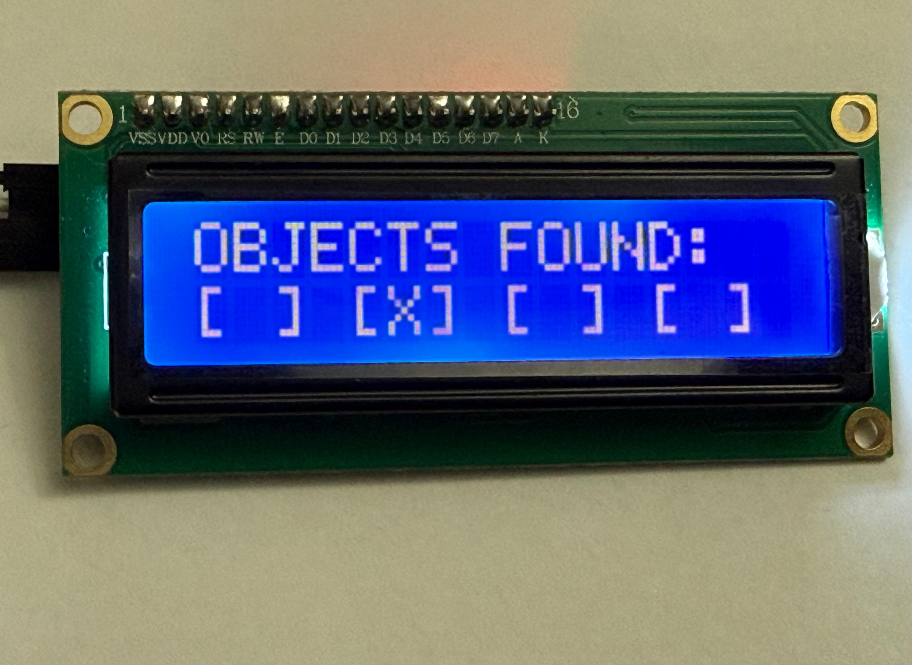
- ›If Objects Found: The LCD maps the threat location (e.g.,
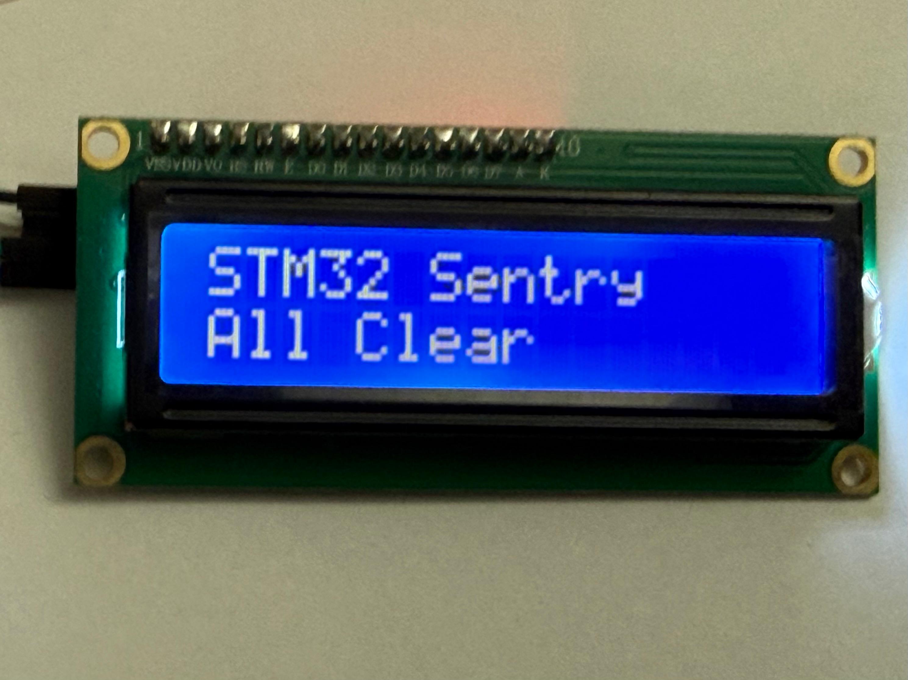
[X] [ ] [ ] [X]). The system resets the servo and immediately re-enters SCAN (Protect Mode) to actively verify if the threat persists. - ›If Clear: The LCD displays "All Clear". A Smart Wait loop monitors the PIR sensor for 1 second. If motion occurs during the message, the delay is aborted immediately to re-arm the system.
Display Logic
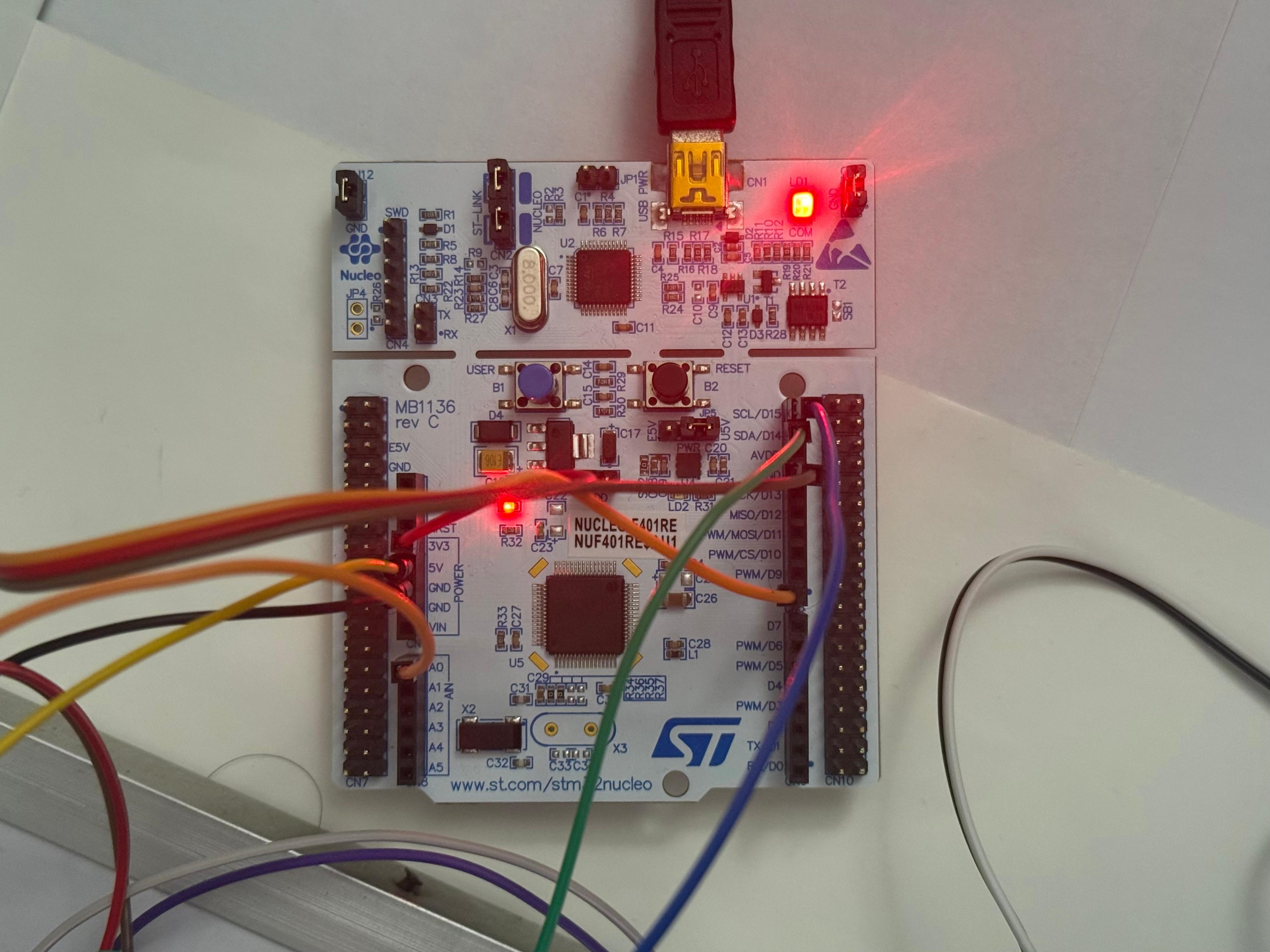
Wiring & Pinout
| STM32 Pin | Component Pin | Description |
|---|---|---|
| PA0 | Servo Signal | TIM2 Channel 1 (PWM Generation) |
| PB8 | LCD/LiDAR SCL | I2C1 Clock |
| PB9 | LCD/LiDAR SDA | I2C1 Data |
| PA9 | PIR Signal | EXTI Line 9 (Rising Edge Interrupt) |
| 5V | VCC | Power for Servo & LCD |
| 3.3V | VCC | Power for LiDAR & PIR |
| GND | GND | Common Ground |
Key Engineering Challenges Solved
1. Whip Pan Bug
Problem: Resetting the servo from 180° to 0° takes physical time (~400ms). The code runs in microseconds. This caused the system to start the next scan while the motor was still flying back to the start, resulting in "ghost" detections on the left side of the room.
Solution: Implemented a non-blocking mechanical settle delay only during the reset phase, ensuring the motor is physically stable before the LiDAR begins ranging.
2. Blind Spot Security
Problem: Using HAL_Delay(1000) to display an "All Clear" message froze the CPU, leaving the system blind to intruders for 1 full second.
Solution: Replaced blocking delays with a while loop that checks HAL_GetTick() but breaks immediately if the motionDetected interrupt flag is raised. This prevents the system from missing a detection.
Build Instructions
-
1. Clone the Repo:
git clone https://github.com/TechNotebookYT/stm32_sentry.git -
2. Open in STM32CubeIDE:
File > Open Projects from File System.
-
3. Drivers:
Ensure
VL53L0Xdrivers andi2c_lcddrivers are inCore/SrcandCore/Inc. -
4. Compile & Flash:
Build Project (Hammer Icon). Run > Debug As > STM32 Cortex-M C/C++ Application.
Future Improvements
- ›UART Logging: Outputting precise distance maps to a Python script for a real-time radar GUI.
- ›Buzzer Integration: Adding an audible alarm during the
NOTIFYstate if proximity is < 20cm. - ›Wireless: Integration with ESP8266/ESP32 via UART to send alerts to a mobile device.